
MaxStream sells several Development Kits that include interface boards and cables for loading firmware upgrades. These interface boards will not connect directly to an XBee that has been soldered to a breakout board, and are rather costly if your only purpose is to upgrade the firmware.
My XBee Firmware Upgrade example demonstrates how to build a bare-bones circuit for loading firmware and configurations to the XBee radio without the need for custom interface boards.
Hi Mr.Rob,
I m somu an engineering student whom is new to this zigbee.I saw your circuit on upgrading/programming new??zigbee but i failed to do so.I made a pcb circuit out from you idea on connecting but every time i tried to communicate with the zigbee a screen pop-up and state “Unable to connect to …”.Why?.I have triple checked the connections and i couldn’t get it.
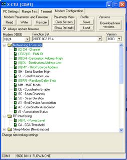
Another thing,in modem config,if i pressed ‘read’ button,another screen pop-up and state ‘Hold the reset button and this screen will go off in 10sec’,do i have to add reset button on rst pin?.
Pls help.I can’t simply get the “Kit” cuz i have no $$$ (=>).Beside i gonna design my own board so the kit is out of my way and it’s gonna serve nothing in my project plus it too expensive.
Pls help.Thanks.
try using a 74HC04, instead of 7404 that’s listed.
Good luck.
Thanks for the info. I want to use the XBee radio to drive a couple LEDS and to do some simple logic processing without adding a Microcontroller. I’ve looked at the Maxstream development boards, but I don’t know how difficult code development is with that development kit without purchasing it.
How can I add code to Xbee to light up a simple LED or do some logic processing on inputs before sending out? Do you have code examples on how to get started? Can I use your firmware upgrader to load code? Thanks!
Check out the I/O commands in the XBee User Guide for information on using the output pins.