Upgrading Firmware for XBee Radios |
|||||||||||||||||||||||||||||||||||||||||||||||||||||||||||||
|
XBee radios are currently in active development and new features are being added regularly. MaxStream sells several Development Kits that include interface boards and cables for loading firmware upgrades. These interface boards will not connect directly to an XBee that has been soldered to a breakout board (as shown here), and are rather costly if your only purpose is to upgrade the firmware. The following example demonstrates how to build a bare-bones circuit for loading firmware and configurations to the XBee radio without the need for custom interface boards. It is based upon information from this MaxStream schematic and has been tested successfully at 9600 baud. |
|||||||||||||||||||||||||||||||||||||||||||||||||||||||||||||
Practical ExampleMinimum parts needed: (see Tom Igoe's parts list for additional details)
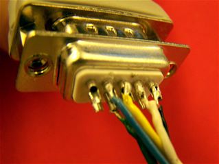
Step 1: Solder five wires to the 9-pin D-sub connector according to the chart below. Solder the opposite ends of these wires to a male header. Here's the connections you'll be making, via the hex inverter:
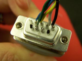
Connections to the 9-pin D-sub female connector, two different views.
Connections to the male header, in this case left to right: RTS, DTR, RX, TX and ground.
|
|||||||||||||||||||||||||||||||||||||||||||||||||||||||||||||
| Step 2:
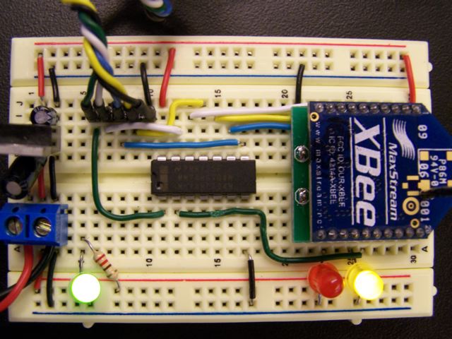
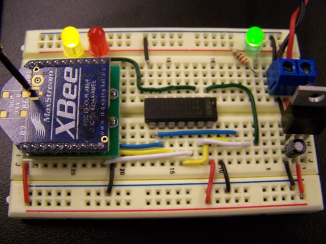
Set up the breadboard with a 3.3 Volt regulator for powering the XBee radio and the hex inverter. The 3.3V regulator used in this example is arranged (from left to right) Ground-Output-Input, which is different from a 5 Volt one. Note that the blue RX-to-DataOut connection is reversed at the hex inverter from the other connections. This is because data is flowing in the opposite direction (from the XBee back to the computer) on the blue wire.
TOP VIEW: XBee running on 3.3 Volt regulator with hex inverter set up to translate between RS-232 and TTL levels.
ALTERNATE VIEW: XBee running on 3.3 Volt regulator with hex inverter set up to translate between RS-232 and TTL levels.
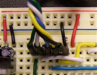
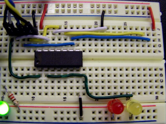
CLOSE UP with XBEE REMOVED: Hex inverter set up to translate between RS-232 and TTL levels.
|
|||||||||||||||||||||||||||||||||||||||||||||||||||||||||||||
| Step 3:
a) Connect the serial connector from Step 1 to the circuit layout created in Step 2 as shown in the TOP VIEW photo above. b) Plug in the power supply. When the Xbee has power the red (ON) LED should light up steady and the yellow (Associate) LED will flash. c) Use a regular 9-pin serial cable to connect from the circut board's 9-pin female plug to a Windows computer's serial port. d) Download the X-CTU installer from MaxStream onto this Windows computer, install it, and launch the X-CTU program.
|
|||||||||||||||||||||||||||||||||||||||||||||||||||||||||||||
| Step 4:
Using the PC Settings tab in the X-CTU program, select the COM port with the circuit connected to it. Most often this will be COM1. The default settings are 9600, 8N1 and no flow control. Unless you have changed to another baud rate or configuration on the XBee that you are programming, these default settings should be fine. Test communications by pressing the Test/Query button on the PC Settings panel. If this test doesn't succeed, carefully check your wiring and solder connections before proceeding. X-CTU PC Settings panel, for configuring and testing connectivity to the XBee radio. |
|||||||||||||||||||||||||||||||||||||||||||||||||||||||||||||
| Step 5:
Using the Modem Configuration tab in the X-CTU program, press the Read button to load the current configuration from your XBee radio. (If you would like to reset everything to the factory defaults, press the Show Defaults button.) Download new versions of firmware, by pressing the Download new versions... button and selecting Web to load them directly from MaxStream's web site. To upgrade to the latest firmware, select the Version that you would like to load (typically the latest and highest numbered version using the pop-up list on the right side of the Modem Configuration panel. Next, click the Always update firmware checkbox to select it. Finally, press the Write button to send the displayed configuration and selected version of firmware to the XBee radio modem. Repeat this step as needed to upgrade additional XBee radios. X-CTU Modem Configuration panel, for configuring settings and upgrading firmware on the XBee radio. |
|||||||||||||||||||||||||||||||||||||||||||||||||||||||||||||
This page created by Rob Faludi |